Thrust Vector Control: TVC
To create our lander, we are going to need to be able to vector our thrust in order to stabilize the system against wind or to offset weight. This milestone will be just in order to test our capabilities. Below is a mock-up of what the actual rocket engine will look like and behave.
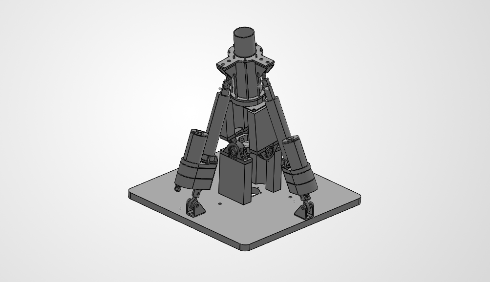
The CAD is easy. Programming is the difficult part.
After talking to a professor, he said the best approach is to work through it in a MATLAB script and create a mathematical model of where my Linear Actuators are planning to go for both Pitch and Roll. But because this is also a team project, we have a live, running Word doc that is used to document all the progress within.
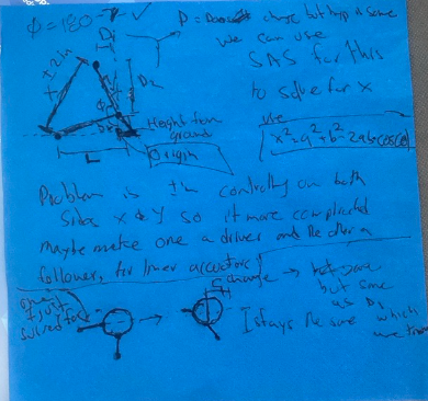
To the left, here are the initial mathematical decisions that I made to be able to create a mathematical model of the linear actuators on MATLAB. It was difficult to understand, but it pointed us in the right direction to be able to create some equations in MATLAB. Below is a link to the current Word document with all updated live values. The drawings have improved since.
MATLAB Mathematical Model
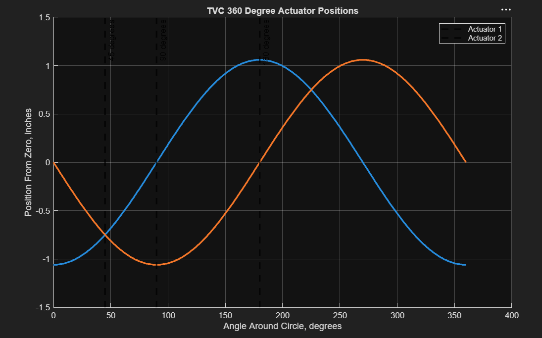
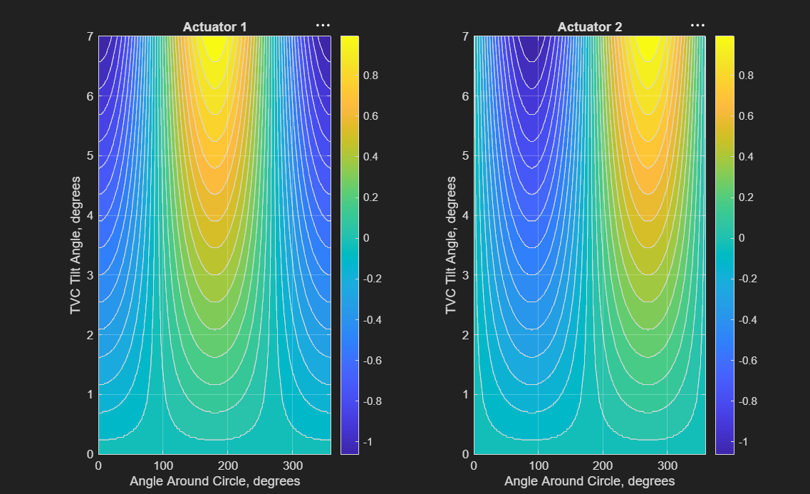
The equations were very basic, something you could solve within a couple of hours of thinking; they just used principal trig equations and geometry to solve for a linear actuator at different pitch angles. All we needed were a lot of initial values in order to fully define our system and be able to solve for 1 variable. To the right and below are the 2 models that I created; one just plots the position of the linear actuator at a steady 7-degree pitch. And the other is a mesh diagram that incorporates all degrees of pitches 0-7.
EE Diagram/Testing
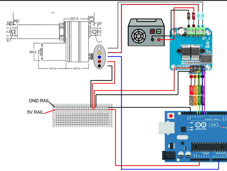
With the mathematical model done, we had to start with the linear actuators, which needed an EE diagram to prove that we wouldn’t overvolt any electronics or shock ourselves by wiring electrical components incorrectly. There are two linear actuators, but we really only need to create 1 diagram and then use different Arduino pins for the other linear actuator to hook up to.
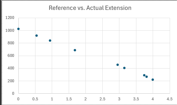
This testing was just to determine whether our analog output from the linear actuators had a linear, logarithmic, or exponential pattern so we could easily understand where we are compared to where the analog signal believes it is. From the test, the system is clearly linear, just inverted, which means that my positive and negative terminals for power were switched.