Thrust Chamber CAD/Drawing
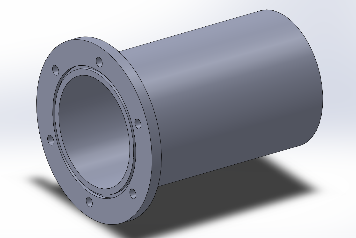
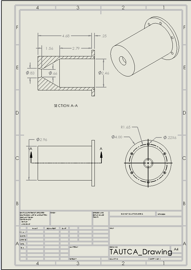
We created this drawing as a quick reference for machining the internal geometry on the lathe. It includes all measurements derived from the MATLAB script, along with a ¼-inch outer diameter to ensure that our 5-second burn would not melt the thrust chamber before shutdown.
We used six 10-32 bolts around the perimeter to ensure the entire assembly fits together securely. Additionally, we incorporated an O-ring groove to prevent flames from escaping through the sides of the chamber during hot-fire testing.
Safety: After our first Preliminary Design Review (PDR), we were informed that our initial design could allow flames to escape at the interface between the injector and thrust chamber. To address this, we added an O-ring to create a proper seal and ensure safe operation.