These are our injector plates, consisting of a top and bottom plate. The top plate is where the oxidizer and fuel are fed through, and it also contains the threaded port for the igniter. The bottom plate is where the oxidizer and fuel mix, and where the igniter spark enters to initiate combustion. This injector uses an impinging design, which is a very common approach due to its ease of manufacturing and relatively straightforward calculations, allowing for consistent results. The fuel flows through the inner manifolds, while the oxidizer is routed through the side manifolds.
Design Review & Challenges:
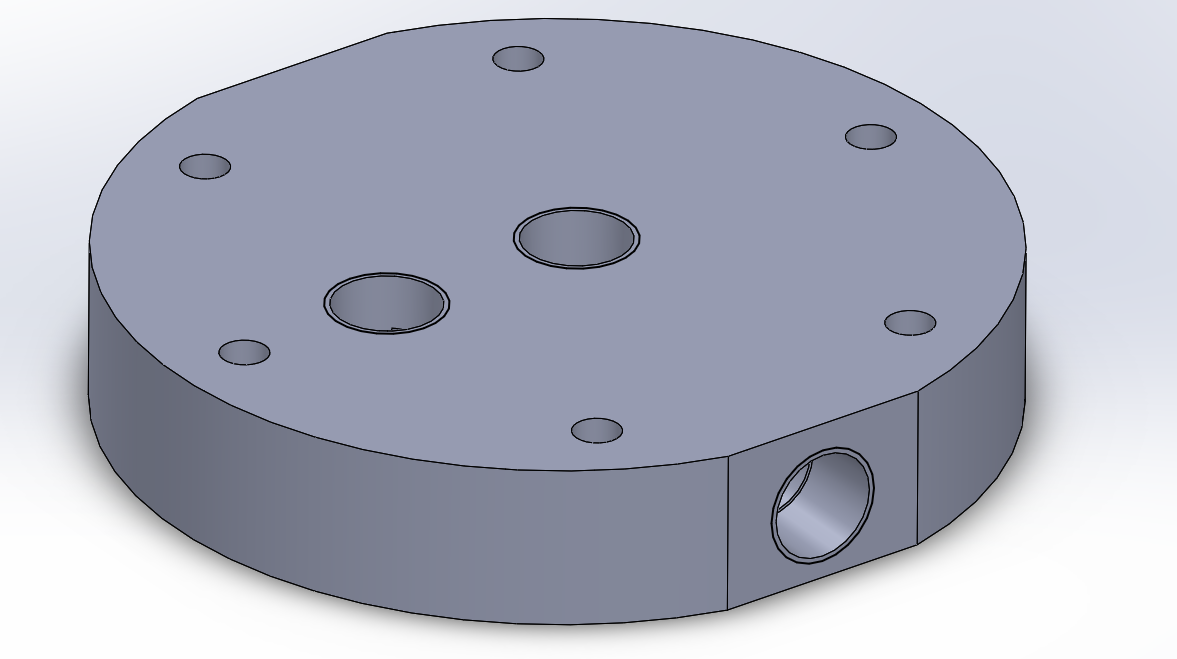
We have three ¼” NPT taps on the top injector plate: one for nitrous oxide, one for ethanol, and one for the igniter. A major challenge with this design came from the test stand, which uses flex hoses with a 1-inch diameter. This required the two top ¼” NPT taps to be at least 1 inch center-to-center apart.
This constraint was difficult to meet given our 4-inch stock limitation, which ultimately led us to offset the igniter from the center. While this does not significantly impact performance, it does make the design less visually symmetric. It also introduced some irregular geometry in the first manifold, as the NPT tap is very close to intersecting the oxidizer manifold.
We also incorporated flat sides into the design to simplify machining. This allows the part to be securely held in a vise without requiring custom round jaws. This design choice was carried over to the bottom plate as well.
Design Review & Challenges:
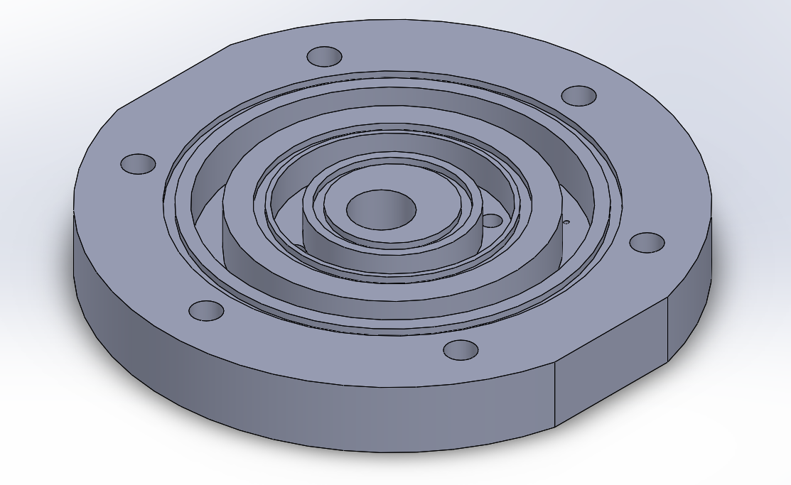
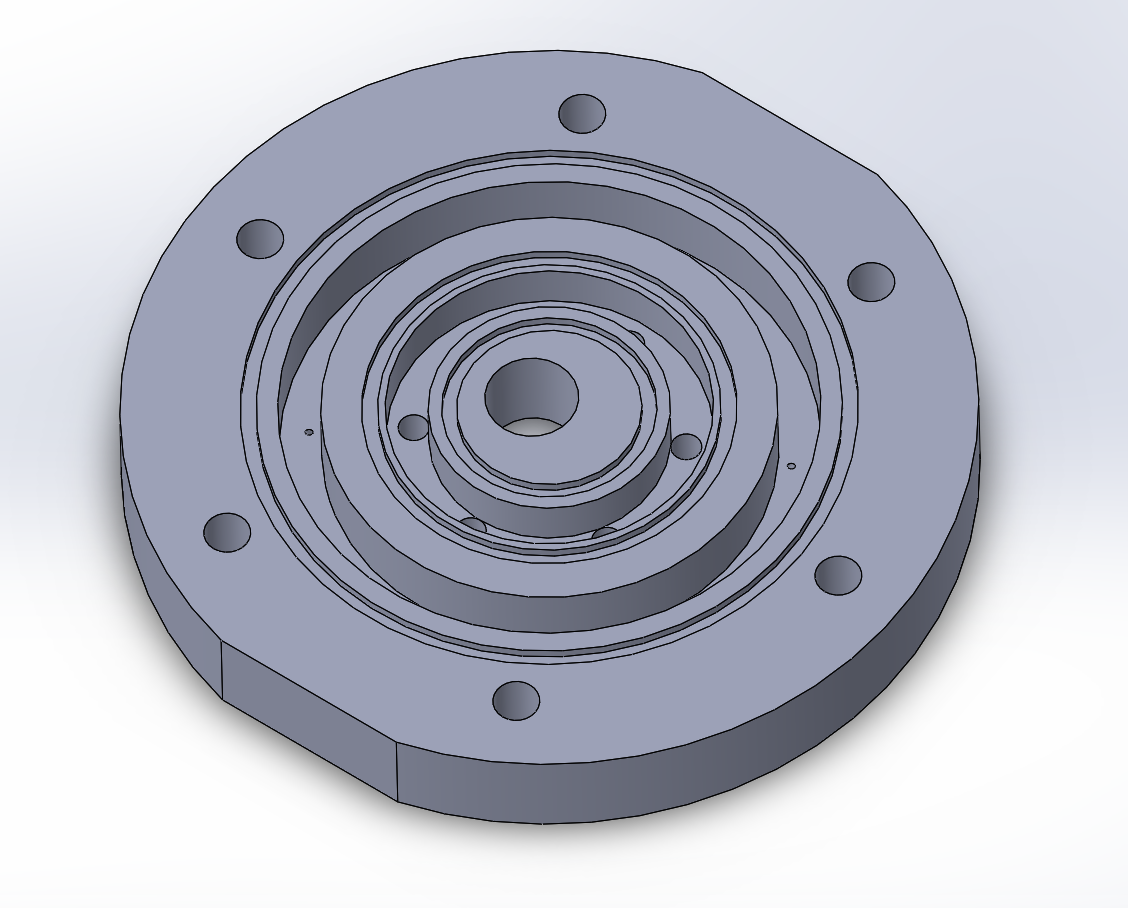
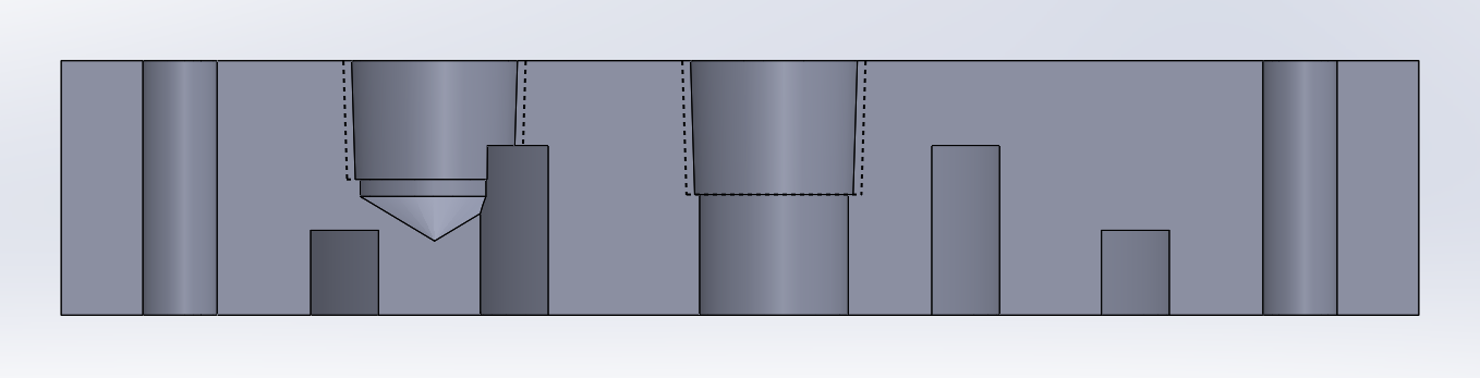
These are section views of our top and bottom injector plates. As shown, there is some irregular geometry where the fuel enters the manifold. I haven’t taken a fluids course yet, so I’m not fully certain how much this disturbs the fuel flow. However, I was more concerned about avoiding issues on the nitrous oxide side, as it is more prone to cavitation, which can be very damaging to the injector since it creates small, localized pressure spikes.
Because of this, I would want to properly test the injector spray pattern and timing to ensure consistent performance and to avoid issues such as hard starts or flameouts.
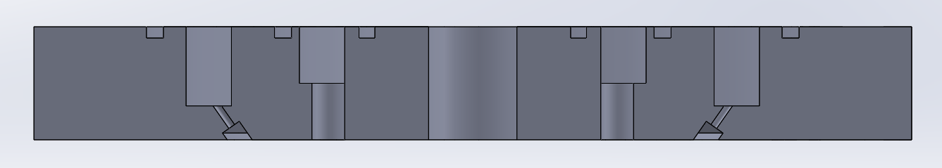
We incorporated O-rings on all fluid interfaces to prevent premature mixing, which could otherwise allow a flame to propagate back through the lines. As shown, this is an impinging injector design, with the oxidizer injected at an angle to promote effective mixing with the fuel.
Design Review & Challenges:
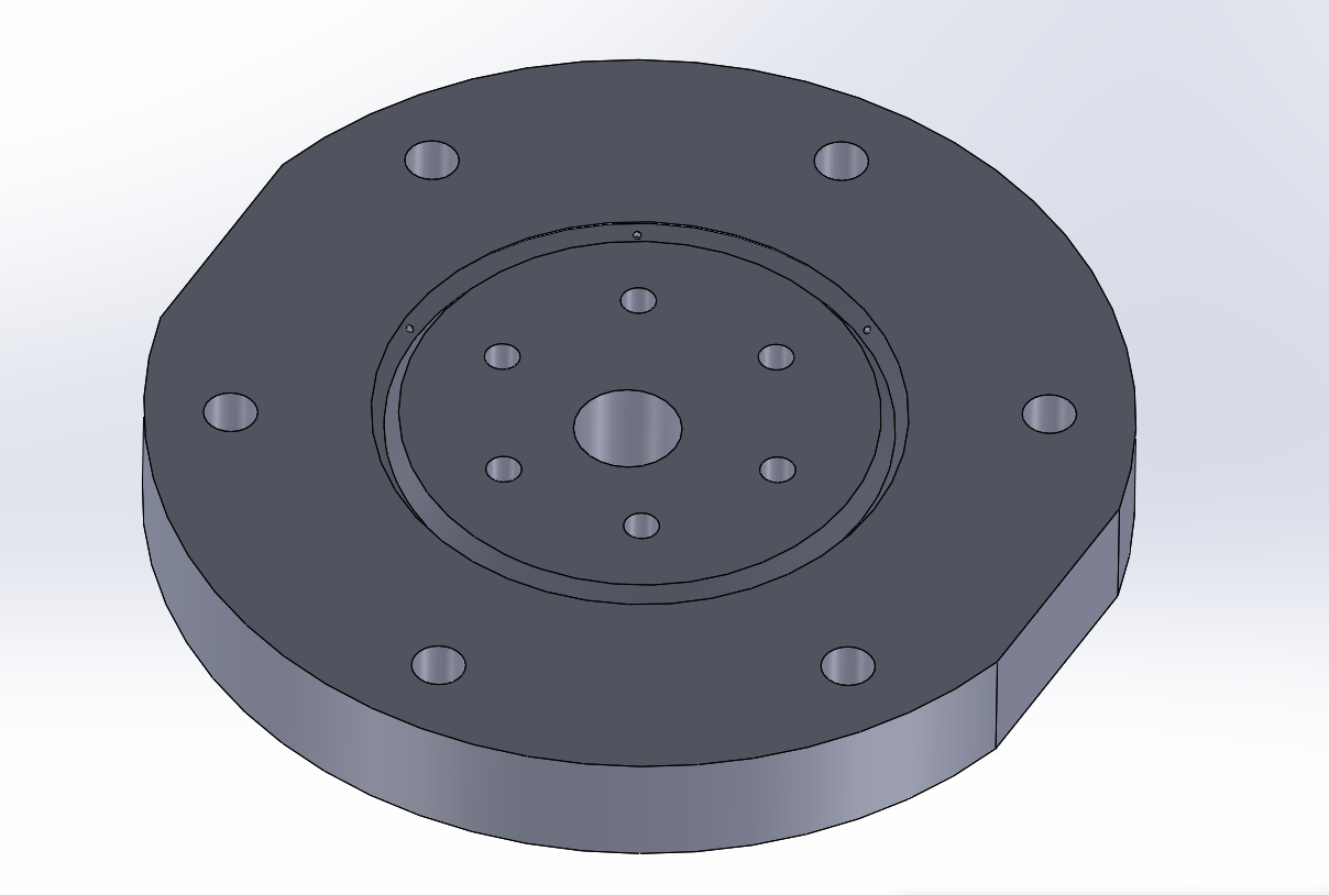
This is the bottom injector plate, which is the most complex component of the engine. The oxidizer and fuel orifice holes require extremely tight tolerances to ensure we do not exceed the desired mass flow rate, as that could lead to inaccurate test results.
It also features an angled surface at the bottom, which allows us to more easily drill the orifice holes for the oxidizer.